
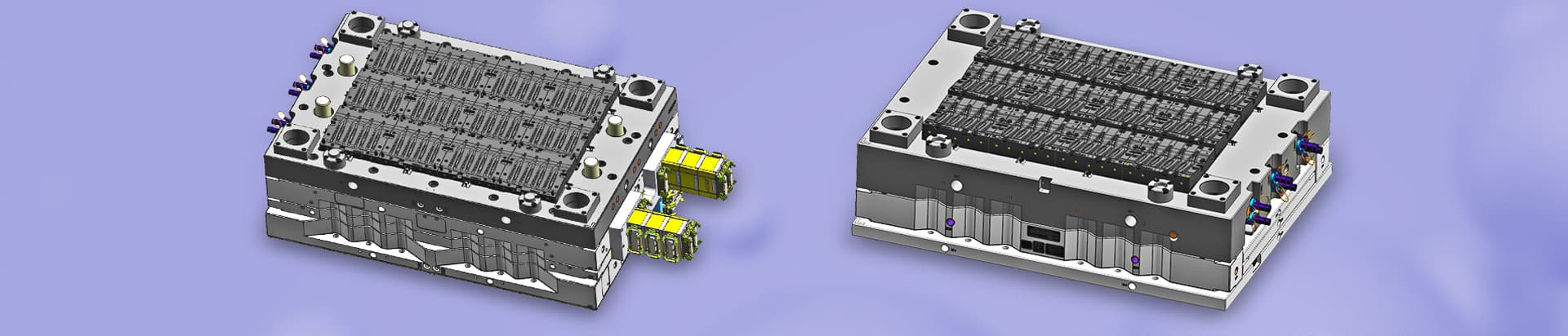
The injection mold runner system includes the main runner (SPRUE), runner (RUNNER), cold well (COLDWELL), and gate (GATE).
The main flow channel of injection molds can be understood as the flow channel of molten plastic from the nozzle of the injection molding machine to the diversion channel. The core function of the mainstream channel is to serve as the primary channel for the molten material to enter the mold, responsible for connecting the injection machine nozzle with the diversion channel, ensuring that the molten material is quickly and accurately introduced into the subsequent flow channel without any retention.
More than 80% of injection molding defects (such as weld lines, shrinkage dents, warping deformations, etc.) are directly related to improper design of the flow channel system.
The cross-section adopts a conical structure, and the demolding slope α is taken as 1-3 ° (1 °~1.5 ° for low viscosity and easy to flow materials such as PE/PP, and 2 °~3 ° for medium high viscosity and difficult to flow materials such as PC/PVC), which facilitates the smooth demolding of the aggregate. The inlet diameter d and outlet diameter D need to meet the gradient requirement of D-d=0.5~1.0mm to avoid the formation of a retention zone for the melt in the flow channel. The radius R of the sprue sleeve ball should be greater than the radius r of the injection machine nozzle ball. It is recommended to design a difference of R=r+0.5~1mm to ensure a sealed fit during the injection process and prevent melt leakage.
The main channel diameter of injection molds is mainly determined by the injection volume of the injection molding machine (and the size of the matching nozzle), which is a priority equipment matching condition that must be met.
The main channel small end is directly connected to the injection molding machine nozzle, with a diameter slightly larger than the nozzle hole, usually the nozzle hole diameter+0.5-1mm, in order to prevent overflow, compensate for thermal expansion, and avoid obstruction of melt flow. In addition to equipment matching, products and materials also affect actual values: the thicker the product wall, the larger the main channel can be correspondingly increased; Plastics with poor fluidity (such as PC, PMMA) require a larger diameter to reduce flow resistance, while plastics with good fluidity (such as PE, PA, PP) can be appropriately reduced.
Diameter calculation: Small end diameter=nozzle aperture+0.5-1mm; large end diameter expands outward at a cone angle (generally 2 ° -6 °) to facilitate the demolding of the aggregate.
Length control: The main channel length should be as short as possible, usually not exceeding 60mm, to reduce pressure loss and heat loss.
Conical design: The main channel needs to be made into a conical shape with a cone angle of 2 ° to 6 ° to ensure that the material in the channel can be smoothly pulled out.
Common range: The diameter of the small end is generally taken as 4-8mm; when the wall thickness is 6mm or more, the diameter of the flow channel can reach about 9mm, but the larger the diameter, the better. If it is too large, it will waste materials and prolong the cooling time.




 Call us on:
  Email Us:
  1st Floor, Block1, No.3 Beiting Road, Houting Community, ShaJing Street, Bao'An District, Shenzhen City, Guangdong Province, China
  English
 Deutsch
 italiano
 русский
 français
 română
 العربية
 Español
 Polska
 日本語
日本語 한국어
한국어